Wednesday, April 15, 2009

Structural Study IV

A number of days after the model
was tested for weathering and
human interaction, the model's
concrete was examined for
structural integrity. The tubes at
the model's foundation which
contained concrete were
disassembled for observation. The
exterior tubes were sawed both
lengthwise and widthwise to
reveal the concrete. Some of the
tubes were even removed
completely to reveal a concrete
mold. The concrete revealed that
over a number of days, it did not
fully cure. For example, some of
the innermost concrete was
slightly moist to the touch. This
lesson taught us to either allow
ample time for the concrete to
dry in the foundation of our future
model, or measure each ingredient
in the concrete-making process
with more precision.

-Tim, Matt, & Phil

Site Information II

Here is the analysis diagrams for the views and users around the site. The first diagram shows direction of view determined by proximity of closeness (close in dark grey, intermediate in medium grey, and far in light grey) and type of view (people in pink, structure in blue, and nature in green).


The second diagram shows the NE view where the same color coordination defines the type of view.
The next diagram shows how the user groups circulate throughout the immediate site at high and low activity.

The final diagram overlays the analysis of the view and the analysis of the user to determine the best location for the design.
-Aaron and Val

Tuesday, April 14, 2009

Charette II

On April 13 we sat down as a class for a second time to update everyone on all the group studies. Val and Aaron presented their information on the site location and we used that to help us get a conversation started on what the design should be. One important analysis was of the views from our site. We felt it was important to appreciate these views in an effort to connect our structure and the user with not only the site it is directly sitting on but also with various parts of the city. We also decided that an abstract form would be more appropriate for this site. The site has many formalities and we felt a literal structure would be lost and/or expected. Rough sketches of the idea we are currently developing can be found below. The structure will "grow" out of the ground gradually with multiple "tentacles." The tentacles will serve as planters in order to blur the line between the land and our structure. Each "tentacle" is a gesture toward a view we find important. Our hope is to direct the user's attention toward these views in a discreet manner. The structure will also serve as a seating area. There will be multiple seating areas allowing for users to break. Though there are many benches along the site we felt that it was important to create a structure that the user could interact with. We are also talking about designing a canopy over the seating areas that will add another level and layer to our design.


Charette I

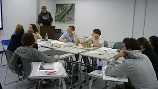
Our first class charette was on April 6. Everyone came in with study models of their own personal "cardboard pipe dream" We discussed what we thought were the strongest parts of each and what were the weakest. Some envisioned the structure to be organic and light while others saw it as a mass that was carved into. At the end of our first meeting there were still disagreements as to what direction the project should go in. We decided it was important to continue our material studies and see what limitations we had and what these tubes are capable of before making a final decision on what we wanted to create.


Presentation of initial ideas unveiled in an energetic in class discussion.


The "hand/canopy" solution challenges what might be possible and gravity and looks exciting.


A solution taps into the mass of the tubes to build an undulating structure.


Each tube in this design points to a different view of the city, and doubles as a jungle gym. Can it be build strong enough?


Another massing solution with vertical tubes, fitted together like a jigsaw puzzle.


A "lounge chair" design utilizing another massing scheme.

Monday, April 13, 2009

Site Information I

The location for this project was chosen after a series diagrams and extensive research by myself and Aaron into the various views to and from the site as well as the user groups who make use of the site. The first three panoramic photographs were taken to show some selected views. The first two views are from the site looking back at the city and the third panoramic is looking down from the bridge onto the site.


These images are taken from a PowerPoint Aaron and I put together in regards to user groups, breaking them down as specifically as possible as well as adding reasons for use.


The research and the diagrams that Aaron and I drew ultimately led us to selecting the south boundary of the River Park for our installation.

research by Val and Aaron

Structural Study III

After determining the structural integrity of each structural connection, an attempt was made at constructing a full-scale study model. First, a base was created and concrete was poured into the bottom of four tubes. Then a series of tubes were fastened together by the successful methods of the previous connection studies. Next, the object was placed at the intersection of walking paths on the PhilaU campus.

The device was created to monitor how people react and interact with such an object. The structure also served as a material study to observe the affects of rain, wind, etc. Over a 72 hour test period which included elements such as rain and wind the structure began to wilt and deteriorate at certain points.
Here is a detail picture of our construction, showing the angle for a potential armature and the ballasting. To add weight and strength we added concrete infill to the tubes. We also coated the tubes in an acrylic based sealer.


- Tim, Matt, Phil & Sheila

Structural Study II

Taking what we have created and observed from Structural Study I, more advanced models with more realistic means of connection were created:

A. 90 DEGREE COUPLING
Two tubes meet at a right angle, with each tube notched for one
to fit into the other. The two are fastened together with a
single screw through the intersection of the tubes.


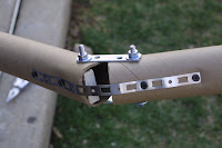
B. ADJUSTABLE ANGLE CONNECTION
Advanced version of model E in Structural Study I. One rod
is driven through the ends of two tubes, with each tube
connected by small metal plates at the ends of the rod.
The model is free to pivot about the metal plates.


C. "TRI-POD CONNECTION"
Similar to that of model B. Three tubes are joined together
by metal rods and plates. Each tube is free to pivot, allowing
multiple opportunities for angular construction.


D. LINEAR ELONGATION METHOD I
Exterior metal bracing joins two tubes at their ends. The tubes
are fastened by screws through the bracing and the tubes.


E. LINEAR ELONGATION METHOD II
Interior of tubes contain small wooden blocks with screws driven through
the blocks and each side of the tubes. A more sturdy and successful
elongation method compared to model D. Will allow for longer spans of
tubes.


- Tim, Matt, Phil & Sheila

Wednesday, April 8, 2009

Structural Study I

Finding the most effective way to fasten one tube to another is a vital step in the design and construction process. Each of the connection studies vary in strength, materiality, functionality and aesthetic appeal.

A. ROPE - Two tubes are tied together with rope
wrapping around and between each tube. The
tubes are fixed and remain parallel


B. DOWEL ROD - A single dowel rod is simply drawn
through previously drilled holes in each tube. The
tubes are able to pivot around the rod.


C. NUTS & BOLTS - A metal rod passes through
two tubes. The tubes are tightened together with
nuts and washers. The tubes are able to pivot
around the rod.


D. PLASTIC TIE - A black plastic tie is drawn
through holes, and wrapped around one side
of the pair of tubes. The tubes are fixed and
remain parallel


E. CARDBOARD PLATES W/ DOWEL RODS
Each tube has one dowel rod driven in through
holes toward each tube's end. The two tubes
are brought together at the ends with a small
piece of cardboard pierced by the rods and
fastening the two together. Each tube's rod is
able to pivot about the cardboard plates.
- Tim, Matt & Phil

Precedents I

At the start of the project everyone began to look at precedents and other cool projects that were made out of cardboard. Here are some..
Public Farm: Interactive Urban Gardening
This was an installation that was located outside of Ps1 Gallery run by MoMa. They used industrial sized cardboard tubing and created a system to hold the plants in them.

On the bottom it was more of a park setting with cardboard chairs holding plants and grass in them.

This installation was part of P.S. 1's ongoing annual YAP, Young Architects Program, which challenges architects to compete in designing a temporary structure to be installed every summer at the facility.

During Construction.


Finished Product.


DuneScape By: SHoP

This installation was done at the same location as the urban garden. It was installed during the summer of 2000 and was built using stick frame construction. Its considered "blob-itecture" because of the different sectional quality every 4 inches.


Cardboard Room
This project was made out of cardboard sheets that were subtracted from to form this beautiful flowing room.

-Christine

Materials Studies II

Over the past few hours we have been testing the tube's resistance and properties after being exposed to water.

After full saturation with water, the material begins to lose cohesion and unwrap from it's spiral form.

Another view of the material failure at full saturation.

Water testing site with the materials placed at timed intervals for exposure and saturation testing.

The cardboard when wet, but not thoroughly saturated, starts to weaken and crush. We have also found that when allowed to dry it returns to it's original strength without noticeable side effects. Next we will try treating the cardboard with a sealer to make it more water resistant.

-Ryan & Nicole