Wednesday, April 29, 2009

Final Model: Phase I

Hey, it's starting to look like something!

On Sunday the 26th and on the
following day during our regularly
scheduled class time, everyone
assembled at Phil's house. We all did
our part incompleting different aspects
of the final model.

Some people worked on the bases,
others worked on the wood knuckels,
and the rest worked on the canopy.

Each base was made the same was as
the base seen in "Structural Study X".
As mentioned before, each of the bases
project at different angles. As the
bases are lined up, each one stands
10 degrees more than the next. In
order for the arms to support their own
weight, the tubes are appropriately offset
further back on their plywood foundations.

A series of identical wood knuckles were
produced in an assembly line by a number
of students. They're all lined up and
ready to be placed in their tubes! A
couple of these knuckles have already
been placed in the bases with the addition
of another tube, just to temporarily
provide a sense of scale.

Along with the main structural elements,
construction began on the canopy. Some
of the smaller tubes are being cut into 2"
segments. They will be fastened together
and will form a shading device within the
large structural arms.

- Everyone


Sunday, April 26, 2009

Structural Study X

A well-improved version of Structural
Study IX is built. The same type of
carpet tubes are used, and the same
wood joints are placed within the
tubes. As good as the previous
study was, this most recent one is
even better.

First, no rope is needed for tensile
strength. We initially anticipated the
need for roped once again, but we
were pleased when we saw this
structure stand up and support its
own weight.

Second, an effective foundation is
built. The main structure possesses
two smaller tubes that reach the
ground an act the same way as a
bicycle's kickstand. Then, the
structure is screwed down to a
sheet of plywood for balance.

The planned design of the final
model is that a number of these
structures will be built. Each one
will project at different angles, and
will be placed alongside the paved
path at the park at the Schuylkill
River (See "Model I" post). Also, the
seating which can be seen in
Structural Study VI will be built in a
similar way and incorporated within
these structures, creating a
project both sculptural and
interactive.

This study was so successful that
it will be used as part of the final
model. It is now safe to say that
this is the last "Structural Study",
and the project can move onward
towards the final model!

- Tim, Matt & Phil

Friday, April 24, 2009

Tube Contributors

Our project would not be possible if it were not for kind and helpful students, printing companies and architecture firms. We even got some help from carpet companies and fabric stores! We have depended solely on these people to donate hundreds of tubes. Here are the following contributors of tubes to our studio:

AC Repro - 159 tubes
Adams Carpet Center - 6 tubes
Adler's Fabrics - 12 tubes
Agoos Lovera Architects - 20 tubes
Atkin Olshin Schade Architects - 17 tubes
Ballinger - 12 tubes
Blackney Hayes Architects - 65 tubes
Bloomfield & Associates - 7 tubes
Bruce E. Brooks & Associates - 15 tubes
Claflen Associates - 3 tubes
Cogan Joseph J Blue Prints - 31 tubes
Daley + Jalboot Architects - 11 tubes
Floss Barber, Inc. - 16 tubes
Kincus Fabrics - 7 tubes
Matthew V. Piotrowski, Architect - 20 tubes
Metro Architects - 16 tubes
Paulson & Company Carpet Sales - 12 tubes
Philadelphia University Fashion Students - 5 tubes
Reinhart Carpet Outlet - 12 tubes
Runyan & Associates - 36 tubes
Venturi, Scott Brown & Associates - 16 tubes
Weidmann-Zelig Group, LLC - 36 tubes
Wulff Architects, Inc. - 8 tubes
Random Contributions from Other Philadelphia University Students - several

There are links to these firms' and companies' websites up on the right side of our page - please visit them to see their work, or their wide selections of carpet!


Thank you to everyone who helped us out!

-Tim

Thursday, April 23, 2009

Structural Study IX

A rather significant advancement
has been made in order to
provide structural strength to
the project. Since the screws
did not work well in Structural
Study XIII, Phil and Matt
conceived the idea of using large
wooden joints to be placed
within two adjacent tubes for
the canopy pieces. These
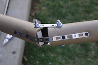
"knuckles" are made of a series
of solid wood pieces screwed
together to form a joint. The
pieces once again form a 145-
degree angle. The knuckles are
easily slid into two tubes, then
screwed into the tubes to increase
strength. The knuckles can also
be easily mass produced, which
will save much-needed time and
labor.

The canopy pieces, however,
can not stand on their own.
Each one needs their own form
of a foundation so they will
not topple over. It is known so
far that something the weight
of Aaron (bottom) will anchor
the canopy in place.

Doesn't that bottom photo remind you of anything?

- Tim, Matt & Phil

Structural Study VIII

With the project being as far
along as it is, we have been
fortunate to have access to
shop equipment, such as table
saws, band saws, sanders,
etc., in Phil's basement. We
have also been provided with
a bundle of carpet tubes much
larger than architectural
plotter paper tubes. With the
shop and these massive tubes,
our possibilities for our final
product have increased
greatly.

A full scale study of the
canopy aspect of the project
has begun. With the large
carpet tubes, a large object
in the shape of a bending
finger is made. They are
joined together at 145-
degree angles, and each of
the three pieces are approx.
4 feet long. They are
fastened with screws into
blocks of wood within the
tubes. This piece failed to
stand up effectively, so ropes
are tied at the joints and run
the length of the piece to
provide tension. The piece
did provide a sense of scale in
relation to people, but it
unfortunately did not possess
the level of structural integrity
we had aimed for.

- Everybody

Saturday, April 18, 2009

Plant Connections Study III


The tubes are shown 1,2,3, and 4 respectively after one week of living in the cardboard tubes.  In one week, they received much rain water and minimal sunlight.  The first plant was in the plastic cup and flourished the best because the water was contained longer compared to the netting of 2,3,4 where the water fell through to the ground.  


This is plant number one, which is the plant that flourished the best.  We have decided on using the cups to connect the plants to the cardboard tubes because the plants can stay alive the longest as well as it is the easiest way to connect them.  Using the cups also allows for people passing by to take a flower if they so desire. 


After some discussion, we decided that it would be best to also use grass as some of our tube-fillers for the plant section of our project. Depending on where the plants go on the project, the grass will start from the structure's lowest tubes and gradually start to be filled in with flowers as the tubes increase in height. Since the cardboard tube aspect of the project has become more of a flowing organic shape, this element of grass gradually turning into flowers brings the entire project together visually.

- Jo & Christine

Structural Study VII

Our studio is contemplating the
idea of including some sort of
canopy to project up and
outward from our main
structure. It will provide shade
for its users, and will also catch
peoples' attention more as they
approach and walk by the
structure. In this study, two
vertical tubes support two more
tubes projecting out
horizontally. Between these
projecting tubes are 2" pieces
of tubing. They are fastened
together with rope and plastic
ties. These bits of tubes provide
a dynamic aesthetic to the
overall project. One notable
feature to this study model is
that the canopy is free to pivot
about the vertical tubes. This
can allow adults and kids alike
to interact more with the
project.

- Tim & Phil

Structural Study VI

A slightly more advanced study
model compared to Study V
has been made. The tubes are
fastened the same way, but
provide a stronger structure
than before. They still provide
an organic form, which is our
object for the final product.

Also, a chair study is created
with the same method of rope
fastening. A bundle of ten
tubes are made, and the ends
are cut to fit the human
physique for comfort.
As you can see at the bottom,
Jo seems to like it!
- Tim, Matt & Phil

Wednesday, April 15, 2009

Structural Study V

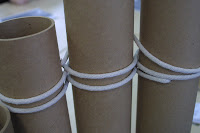
A new progression of how to
fasten tubes together has
been made. Using rope, a
series of eight tubes of various
heights are brought together,
The rope is driven through
holes in the tubes and woven
around each other. This method
allows this composition of tubes
to be moved into multiple forms.
It may be straightened out or
curled up into a tight space.
These forms are fluid and
organic, which are aimed
towards the desired aesthetic of
the final product.

- Tim, Matt & Phil


Model I

Here is the first CAD sketch of our design so far. It is a sculptural gesture focused on the view and user friendliness as determined by the analysis. Our current plan is to have vertical cardboard tubing with ranging heights connected by rope lashing, also an extension of green space will cascade across the tops of the tubes. Seating will form webbing between the arms of the structure. This will provide an overall expansive view while the arms will direct to a specific view. How the design relates to the existing pathway will invite users into the central space while enhancing the overall park experience.


Here is an aerial shot of our design proposal. The interaction with the path and the views is important and will be emphasized with the arms of the structure.


This shows a closer view of our design, there are over 1,000 tubes used in this design proposal.

Structural Study IV

A number of days after the model
was tested for weathering and
human interaction, the model's
concrete was examined for
structural integrity. The tubes at
the model's foundation which
contained concrete were
disassembled for observation. The
exterior tubes were sawed both
lengthwise and widthwise to
reveal the concrete. Some of the
tubes were even removed
completely to reveal a concrete
mold. The concrete revealed that
over a number of days, it did not
fully cure. For example, some of
the innermost concrete was
slightly moist to the touch. This
lesson taught us to either allow
ample time for the concrete to
dry in the foundation of our future
model, or measure each ingredient
in the concrete-making process
with more precision.

-Tim, Matt, & Phil

Site Information II

Here is the analysis diagrams for the views and users around the site. The first diagram shows direction of view determined by proximity of closeness (close in dark grey, intermediate in medium grey, and far in light grey) and type of view (people in pink, structure in blue, and nature in green).


The second diagram shows the NE view where the same color coordination defines the type of view.
The next diagram shows how the user groups circulate throughout the immediate site at high and low activity.

The final diagram overlays the analysis of the view and the analysis of the user to determine the best location for the design.
-Aaron and Val

Tuesday, April 14, 2009

Charette II

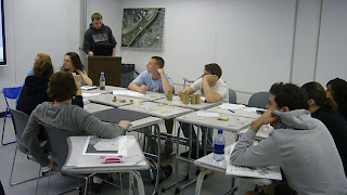
On April 13 we sat down as a class for a second time to update everyone on all the group studies. Val and Aaron presented their information on the site location and we used that to help us get a conversation started on what the design should be. One important analysis was of the views from our site. We felt it was important to appreciate these views in an effort to connect our structure and the user with not only the site it is directly sitting on but also with various parts of the city. We also decided that an abstract form would be more appropriate for this site. The site has many formalities and we felt a literal structure would be lost and/or expected. Rough sketches of the idea we are currently developing can be found below. The structure will "grow" out of the ground gradually with multiple "tentacles." The tentacles will serve as planters in order to blur the line between the land and our structure. Each "tentacle" is a gesture toward a view we find important. Our hope is to direct the user's attention toward these views in a discreet manner. The structure will also serve as a seating area. There will be multiple seating areas allowing for users to break. Though there are many benches along the site we felt that it was important to create a structure that the user could interact with. We are also talking about designing a canopy over the seating areas that will add another level and layer to our design.


Charette I

Our first class charette was on April 6. Everyone came in with study models of their own personal "cardboard pipe dream" We discussed what we thought were the strongest parts of each and what were the weakest. Some envisioned the structure to be organic and light while others saw it as a mass that was carved into. At the end of our first meeting there were still disagreements as to what direction the project should go in. We decided it was important to continue our material studies and see what limitations we had and what these tubes are capable of before making a final decision on what we wanted to create.


Presentation of initial ideas unveiled in an energetic in class discussion.


The "hand/canopy" solution challenges what might be possible and gravity and looks exciting.


A solution taps into the mass of the tubes to build an undulating structure.


Each tube in this design points to a different view of the city, and doubles as a jungle gym. Can it be build strong enough?


Another massing solution with vertical tubes, fitted together like a jigsaw puzzle.


A "lounge chair" design utilizing another massing scheme.

Monday, April 13, 2009

Site Information I

The location for this project was chosen after a series diagrams and extensive research by myself and Aaron into the various views to and from the site as well as the user groups who make use of the site. The first three panoramic photographs were taken to show some selected views. The first two views are from the site looking back at the city and the third panoramic is looking down from the bridge onto the site.


These images are taken from a PowerPoint Aaron and I put together in regards to user groups, breaking them down as specifically as possible as well as adding reasons for use.


The research and the diagrams that Aaron and I drew ultimately led us to selecting the south boundary of the River Park for our installation.

research by Val and Aaron

Structural Study III

After determining the structural integrity of each structural connection, an attempt was made at constructing a full-scale study model. First, a base was created and concrete was poured into the bottom of four tubes. Then a series of tubes were fastened together by the successful methods of the previous connection studies. Next, the object was placed at the intersection of walking paths on the PhilaU campus.

The device was created to monitor how people react and interact with such an object. The structure also served as a material study to observe the affects of rain, wind, etc. Over a 72 hour test period which included elements such as rain and wind the structure began to wilt and deteriorate at certain points.
Here is a detail picture of our construction, showing the angle for a potential armature and the ballasting. To add weight and strength we added concrete infill to the tubes. We also coated the tubes in an acrylic based sealer.


- Tim, Matt, Phil & Sheila